IS-F08
Functions:
1. It can detect max. 8 fans operation.
2. This also can detece the temperature 50℃, 60℃ and 70℃ by yourself.
3. If fan stop working and over temperature, the buzzer should be alarm.
Functions:
1. It can detect max. 8 fans operation.
2. This also can detece the temperature 50℃, 60℃ and 70℃ by yourself.
3. If fan stop working and over temperature, the buzzer should be alarm.
2.Watts:
3.Input:Null
4.Output:Null
5.Dimensions:
6.DownLoad:Null
7.Connectors:Null
8.Features:
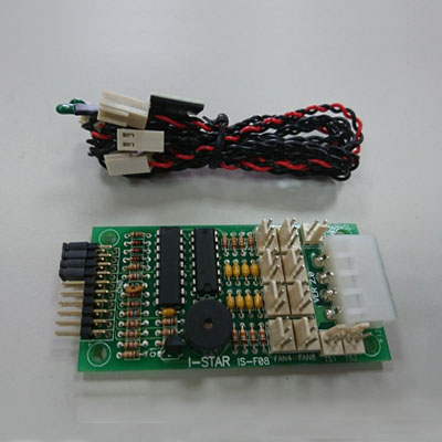
User manual for alarming device
Installation procedures
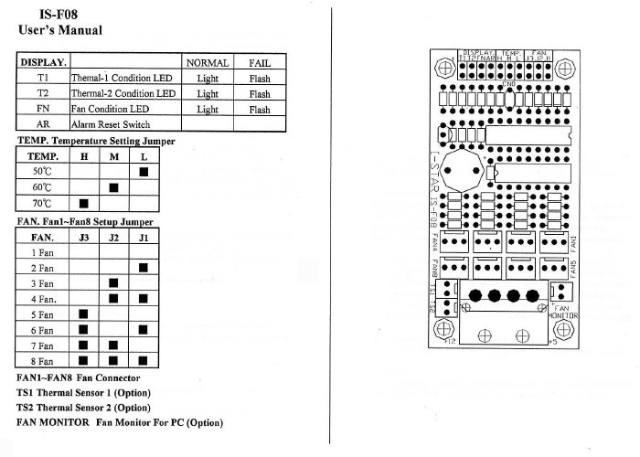
FAN :
Step 1.
To count the total number of fans that suppose to be installed within the PCB board of
alarming device, then study the users manual to learn how to set up the jumper
position according to the manual.
Step 2.
After correct jumper setting, then have the power on for the fan.
Please note: This point is very vital, you have to set the jumper fist, then do the
power on for fans. Otherwise, your setting will be useless. Please disconnect the
power of fan and re-do the jumper setting according to the instruction of user manual
again.
Step 3.
Always connect the first PCs of fan to the first connector for fan in the PCB board of
alarming device. Please make sure the assigned number 1 fan connector of PCB board
is to be connected by your first fan. And please make sure fan connector in the PCB
board has to be used in the order like No.1, No.2, No.3, No.4,…..up to No.8. If you
skip any connector, it will result an appearance like defect condition.
HEAT SENSOR:
(1) Among 3 temp position of 50 degree, 60 degree, 70 degree, please determine which temp is the one to use as a alarming triggle point, then set the jumper position.
(2) In case, you see the heat-alarm go off (normally temp LED stay light, temp LED flashing when triggle ) right after your jumper setting, please check the inside temp of chassis to see if the jumper setting temp is too low, then re-do the jumper to the right position.
(3) Check the heat sensor by high temp object that has temperature higher than the jumper setting, but you see NOTHING HAPPEN, then it may have 2 possibilities such as:
possible defect heat sensor unit, try the next sensor unit to see if it will triggle, than we can determine the first try heat sensor is NO GOOD.
After change the new heat sensor, but the alarm is NOT triggled, then the PCB board need to be changed and to see if the alarm will triggle. If YES, then we can determine the previous psb board is NO GOOD. IF still NO triggle after change the PCB board, then the heat sensor maybe NO GOOD, so please change heat sensor unit with new PCBs board and still can not triggle by same testing procedure, then we can determine the alarming device is really NO GOOD.
Another quick way to determine is the PCB board is NO GOOD by disconnecting the heat sensor connector from alarming PCB board, if the LED still flashing and buzz come on while the fan jumper is in correct setting and fan connectors are connected in the order without any skipping (everything is right, but the alarm is go off), then we can determine the alarming PCB is NO GOOD.
Dear my friend, please try to do the procedure step by step first, you may find the
PCB is not really defect. Please check again by following the above advise.
9.Others Certificates:
| REACH | RoHS 2.0 |
10.Packing
| 100pcs in One carton | N.W. | G.W. | Carton Size |
| IS-F08 | 5.50 kgs | 6.00 kgs | 44 x 31 x 26 cm |
| 12.12 1bs | 13.22 1bs | 17.32 x 12.20 x 10.23 inch |